


A. Ogata ogata@kekvax.kek.jp
National Laboratory for High Energy
Physics
Tsukuba,
Ibaraki, 305
Japan3mm
abstract: Recent experiments have convinced us that plasma
accelerators have very high acceleration gradients.
Our concern has now turned to the question of whether plasma acceleration
can be used in real accelerators or not.
Plasma accelerators are reviewed in order to help this discussion.
The principles of four methods (plasma wakefield acceleration (PWA),
beatwave acceleration (BWA),
laser wakefield acceleration (LWA),
and self-modulated laser wakefield acceleration (sm-LWA))
are given first.
The experimental results obtained so far are then described.
Accelerator issues, such as beam loading, emittance, bunch length and
efficiency, are discussed, and the designs of future linear colliders based
on the LWA are presented.
Recent experiments have convinced those in the field of plasma accelerators that these accelerators have very high acceleration gradients. Their concern has now turned to the question whether plasma acceleration can be used in real accelerators or not. This present paper has two purposes. The first is to present these excellent experimental results to those in the society of accelerator beam physics. The second is to discuss the adaptability of plasma acceleration to accelerators for real use.
A proposal of Tajima and Dawson started the modern history of plasma acceleration[1]. Their paper proposed two laser-based schemes, which are now called beat wave acceleration (BWA) and laser wakefield acceleration (LWA). Because lasers which could meet the requirements of the LWA were hardly available in the 1980's, experimental studies concerning the BWA were started. Several years later, Chen proposed a scheme which uses particle beams instead of lasers in order to excite plasma waves[2]. This scheme is now called plasma wakefield acceleration (PWA). It was soon noticed that the beam-driven and laser-driven methods have much physics in common. It is this PWA which first produced a considerable amount of accelerated particles[3]. Following this, quite a few fruitful experiments on the BWA were reported successively[4, 5, 6].
Meanwhile, the invention of the chirped-pulse amplifier[7]
enabled us to use a high-power lasers
with a pulsewidth of around the wavelength of a high-density plasma wave.
Sprangle called attention to the LWA[8].
The first experiment concerning the LWA was made by the KEK group at
ILE[9]. The so-called ![]() (table-top terawatt) lasers are
commercially available now, which has enabled small laboratories to perform
LWA experiments. A typical
(table-top terawatt) lasers are
commercially available now, which has enabled small laboratories to perform
LWA experiments. A typical ![]() laser uses Ti:sapphire crystals, whose
specifications are a 100fs pulse width, an 800nm wavelength, a 10Hz pulse
frequency and 1-10TW pulse power.
laser uses Ti:sapphire crystals, whose
specifications are a 100fs pulse width, an 800nm wavelength, a 10Hz pulse
frequency and 1-10TW pulse power.
The self-modulated laser wakefield acceleration (sm-LWA) has its roots in Raman scattering[10]. A Russian group and an NRL group have pointed out that the mechanism is positively useful for acceleration, if it utilizes the recent high-power lasers. An experiment at KEK soon followed[13].
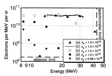
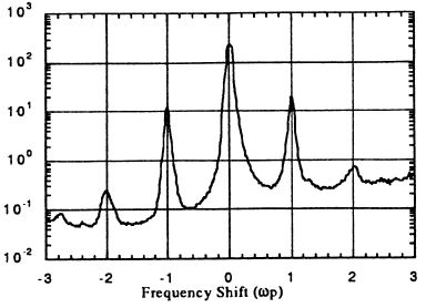
Figure 4.1: Experimental results obtained at RAL. The left figure gives
the energy spectra obtained by various instruments.
The right figure gives the laser spectra.
Figure  shows the results obtained at RAL[14]
based on the sm-LWA.
A laser with a power of 25TW was used.
Since no electron were injected, the results show plasma electrons
trapped and accelerated by the laser field.
The number of electrons accelerated was
shows the results obtained at RAL[14]
based on the sm-LWA.
A laser with a power of 25TW was used.
Since no electron were injected, the results show plasma electrons
trapped and accelerated by the laser field.
The number of electrons accelerated was ![]() and
the normalized emittance was calculated to be 5
and
the normalized emittance was calculated to be 5![]() m for electrons
with an energy of around 30MeV.
A recent report shows that a new detector has detected electrons with
energies of up to 100MeV.
However, most people do not think that this sm-LWA could be a real
accelerator, because the mechanism is too hard to control.
m for electrons
with an energy of around 30MeV.
A recent report shows that a new detector has detected electrons with
energies of up to 100MeV.
However, most people do not think that this sm-LWA could be a real
accelerator, because the mechanism is too hard to control.
Anyhow, those studying the plasma accelerator do not doubt the acceleration in a plasma. The next two sections of the paper give its basis, summarizing principles of plasma accelerators, hitherto experiments, problems and their solutions. Our present concern is the accelerator issues of plasma accelerators, which are discussed in section 4. Linear collider designs based on the LWA are introduced in section 5. The last section contains a discussion.
Plasma accelerators accelerate charged particles using the potential of a
plasma wave.
The field of a linear plasma wave is given by
![]()
where ![]() is the plasma frequency. The field (E) is thus
proportional to the square-root of the plasma density (
is the plasma frequency. The field (E) is thus
proportional to the square-root of the plasma density (![]() ).
This means that a plasma density of
).
This means that a plasma density of ![]() gives
an acceleration gradient of 1GeV
gives
an acceleration gradient of 1GeV![]() .
In a nonlinear plasma wave the field is even larger.
.
In a nonlinear plasma wave the field is even larger.
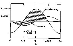
Figure 4.2: Longitudinal and transverse wakefield in plasma waves.
The relativistic sizes of the two amplitudes depends on the radial
position.
The field is excited in a plasma as a wake behind a driver, which is
either particle beams
or laser beams.
The wakefield is generated in both the longitudinal and
transverse directions.
The longitudinal field accelerates or decelerates the test beams,
while the transverse field either focuses or defocuses them.
The test beams should surf-ride on a proper phase of the wave
in order to undergo both acceleration and focusing,
as shown in Fig.[15].
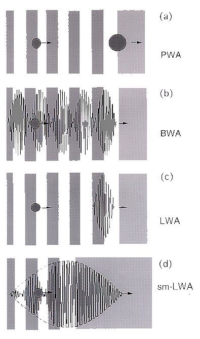
Figure 4.3: Generation of plasma waves.
The background intensity shows the plasma density,
the balls show the particle bunches and
the solid lines show the laser amplitudes.
To be used for acceleration,
the phase velocity of the plasma wave should be nearly equal to the
particle velocity, which is the light velocity for light particles, such
as electrons.
Let us assume here that the test particles are electrons.
We have at least four methods to generate such waves.
They are depicted in Fig..
In the PWA, the repulsion of plasma electrons against beams triggers
plasma
oscillations.
In the BWA and LWA, the ponderomotive force of lasers triggers the oscillation;
the BWA uses two lasers, whose wavelength difference is equal to
the plasma wavelength,
while the LWA uses a single laser with a pulse width nearly equal to the
plasma wavelength.
A parameter useful in discussing the ponderomotive force is the normalized
vector potential of a laser,

where ![]() .
In the LWA, the maximum amplitude of a wakefield is given by
.
In the LWA, the maximum amplitude of a wakefield is given by
![]() ,
while in the BWA, it is given by
,
while in the BWA, it is given by
![]() ,
if we take account of the saturation of the plasma wave,
where
,
if we take account of the saturation of the plasma wave,
where ![]() and
and ![]() are
the normalized vector potentials of the two lasers[16].
are
the normalized vector potentials of the two lasers[16].
The sm-LWA obtained the best results among them.
Its mechanism is rather complicated.
It uses laser pulses which satisfy two requirements:
first, the pulse width should be much longer than the plasma wavelength;
second, its power should exceed the critical power of the relativistic
self-focusing of the laser (![]() ), where
), where
![]()
with ![]() being the laser frequency.
being the laser frequency.
This relativistic self-focusing can be understood as follows;
The refraction index of the laser in a plasma is given by
![]()
The plasma frequency becomes smaller
in a strong laser field,
![]()
where ![]() is the "usual" plasma frequency.
Physically, this is due to the fact the electrons make relativistic
oscillation
transversely in the laser fields, which increases their relativistic mass.
The large a on the laser axis thus gives a small
is the "usual" plasma frequency.
Physically, this is due to the fact the electrons make relativistic
oscillation
transversely in the laser fields, which increases their relativistic mass.
The large a on the laser axis thus gives a small ![]() there.
The refraction index distribution becomes such that the index is
largest on the axis and decreases as r increases.
This distribution focuses the laser.
there.
The refraction index distribution becomes such that the index is
largest on the axis and decreases as r increases.
This distribution focuses the laser.
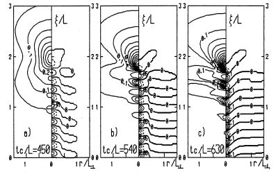
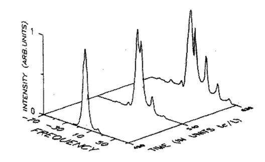
Figure 4.4: Simulation of sm-LWA. The left traces give
contour plots of the laser intensities (left half) and
plasma densities (right half) at three timings.
The right figure gives the laser spectra corresponding the three timings.
a=0.27, laser pulse width normalized by the plasma wavelength
![]() ,
, ![]() .
.
Figure shows a computer simulation of sm-LWA[17].
The left traces give
contour plots of the laser intensities (left half) and
plasma densities (right half) at three timings.
The time proceeds from left to right.
As can be seen, self-focusing of the central part of the laser pulse is
caused first.
Transverse pulse compression causes longitudinal pulse steeping
at a scale of ![]() ,
which triggers the plasma oscillation.
The refraction-index distribution enhances
the laser intensity in the low plasma-density regions,
and reduces it in high plasma density regions.
The ponderomotive force in the high laser intensity region
expels the plasma electrons so as to lower the plasma density further.
A positive feedback-loop is thus created
which enhances the plasma oscillation
and forms beats in the laser waveform.
However, this favorable situation cannot help terminating.
Diffraction of the leading part of the laser pulse ruins the synchronism
between the plasma wave and the laser beat wave.
Two waves then depress each other.
As a result of the whole sequence, the laser frequency is modulated by the
plasma frequency,
which is shown in the right figure.
,
which triggers the plasma oscillation.
The refraction-index distribution enhances
the laser intensity in the low plasma-density regions,
and reduces it in high plasma density regions.
The ponderomotive force in the high laser intensity region
expels the plasma electrons so as to lower the plasma density further.
A positive feedback-loop is thus created
which enhances the plasma oscillation
and forms beats in the laser waveform.
However, this favorable situation cannot help terminating.
Diffraction of the leading part of the laser pulse ruins the synchronism
between the plasma wave and the laser beat wave.
Two waves then depress each other.
As a result of the whole sequence, the laser frequency is modulated by the
plasma frequency,
which is shown in the right figure.
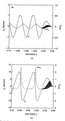
Figure 4.5: Linear(a) and nonlinear(b) plasma waves and their fields.
a=0.5 in (a) and a=2 in (b).
The plasma wave is linear as long as the density perturbation is small;
i.e., ![]() .
A nonlinear wave in which
.
A nonlinear wave in which ![]() can be excited
in the PWA using drive beams
in which the electron density is higher than in the plasma; i.e.,
can be excited
in the PWA using drive beams
in which the electron density is higher than in the plasma; i.e.,
![]() .
It is also possible in the LWA using a laser with a high power density;
rigorously, if its normalized vector potential exceeds unity, a>1.
The sm-LWA drives nonlinear waves even if a<1.
As shown in Fig.[18], a nonlinear wave
makes its amplitudes larger,
the plasma density perturbation impulsive,
the electric field triangular,
and the plasma wavelength longer.
In the BWA, the nonlinear plasma wave soon saturates,
because the beat wavelength is fixed, while the plasma wavelength
increases.
.
It is also possible in the LWA using a laser with a high power density;
rigorously, if its normalized vector potential exceeds unity, a>1.
The sm-LWA drives nonlinear waves even if a<1.
As shown in Fig.[18], a nonlinear wave
makes its amplitudes larger,
the plasma density perturbation impulsive,
the electric field triangular,
and the plasma wavelength longer.
In the BWA, the nonlinear plasma wave soon saturates,
because the beat wavelength is fixed, while the plasma wavelength
increases.
Figure: Experimental results on the plane of acceleration gradient vs.
acceleration length. Territories of conventional linacs, PWA, LWA/BWA and
sm-LWA are given. Two dashed lines show linits of the LWA.
![]() m is assumed in the calculation of the dephasing limit and
m is assumed in the calculation of the dephasing limit and
![]() is assumed in thecase of the pump depletion
limit.
is assumed in thecase of the pump depletion
limit.

The hitherto obtained main experimental results are
summarized in Table 1 and plotted in Fig. .
This table gives only two results for each method, the first and best
results.
A more comprehensive table can be found in a review by Esarey[16].
In the figure, the horizontal axis is the acceleration gradient and the
vertical axis is the acceleration length.
The energy gains are expressed by straight lines on the figure.
The area limited by arrows shows the possible region by laser methods.
The PWA is free from this restriction.
One drawback of laser accelerators is their short acceleration length.
The acceleration length is limited
by the shortest among the three below.
First is the diffraction length or the depth of focus of the laser.
Acceleration is possible only around the focal point of the laser.
If we loose the focus, the acceleration length can be lengthened,
but the acceleration gradient becomes weak instead.
The total energy gain cannot be increased.
A parameter which expresses this length is the Rayleigh length,
![]()
where ![]() is the rms focus size of the laser.
is the rms focus size of the laser.
The second is the dephasing length.
It is the distance in which accelerated electrons outstrip the laser
wakefield,
and is given by
![]()
This limit is caused because the group velocity of a laser in a plasma is
given by ![]() , which is smaller than
the light velocity.
, which is smaller than
the light velocity.
The third is the pump-depletion length in which the laser loses its power.
One expression of this length given by Bulanov et al.[21] is

The standard LWA is limited by diffraction, while the sm-LWA is often
limited
either by dephasing or by pump depletion.
The acceleration observed at the RAL experiments was first assumed to be
limited by dephasing. However, simulations gave a longer acceleration
distance
than eq.() does.
Since their plasma length is very short, around 2.5mm,
the gradient is at least 40GeV/m, still very large.
As shown in Fig., the dephasing length and the pump-depletion
length are long enough in plasmas with moderate density,
so our effort has been aimed at exceeding the limit of the diffraction.
One way is to go into a regime in which relativistic focusing is effective.
However, another way in the nonrelativistic regime has already been
adopted in industries.
Let us recall optical fibers,
in which lasers can propagate without diffraction.
The refraction index of an optical fiber has a transverse distribution,
in which the index is maximum at the core center, and minimum at the clad.
If we could produce a similar index distribution in a plasma
normal to the laser axis, the laser would propagate without diffraction.
The refraction index in a plasma has already been given in eq.(),
which shows that a plasma density distribution with a minimum at the laser
axis will
realize index distribution suitable for laser propagation.
Such an optical channel has been successfully produced by Durfee and Milchberg[23]. They used another laser to produce the channel, besides the laser to excite the wakefields. This pre-laser pulse, focused by axicon optics, prepared a shock-driven axially extended radial profile in the plasma-density distribution. The main laser, injected at the proper timing, was guided by the preformed channel for 24 times of the Rayleigh length. It should be noted that there exists some unknown physics concerning laser propagation in plasmas. which is not necessarily pessimistic. For example, propagation beyond the diffraction limit has recently been reported with a laser power below the critical value of the relativistic focusing[24].
A THz plasma wave excited by the LWA has recently been observed independently by two groups, French[22] and Americans[25]. The principle is that of the old Wharton bridge, which interferes two microwaves, one passes through a plasma and the other does not. The resultant interference pattern gives information about the plasma-density distribution. Femtosecond laser waves are used today in place of microwaves, which gave a femtosecond time resolution.
The rest of this section describes experiments on the PWA. The PWA has not attained a larger acceleration gradient than those by laser methods. It, however, has some advantages: it is not limited in either diffraction nor dephasing. Three experiments are now being planned at INP, SLAC and ANL.
The PWA is in principle a transformer
for converting high-current low-energy particle beams
to low-current high-energy particle beams.
Let us write the charge and energy of the
primary and secondary beams as ![]() .
Because of energy conservation, it is constrained by the
relation
.
Because of energy conservation, it is constrained by the
relation ![]() Moreover, if the bunch lengths of the two beams are infinitely small,
there is another constraint expressed by "transformer ratio"
R[15]; i.e.,
Moreover, if the bunch lengths of the two beams are infinitely small,
there is another constraint expressed by "transformer ratio"
R[15]; i.e.,
![]()
This means that the energy gain of the secondary beam is less than twice
the energy of the primary beam.
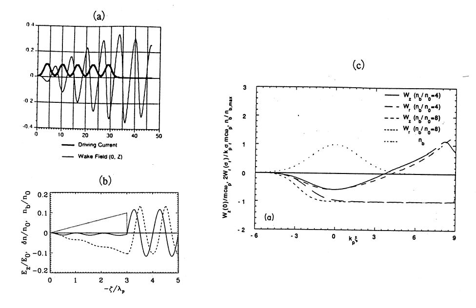
Figure 4.7: Three methods to overcome the limit of the transformer ratio of
the PWA.
There are at least three methods to overcome the limit,
which are shown in Fig..
First is to use drive beams consisting of multiple bunches[26].
The thick line of Fig.(a) shows the drive beam of five bunches.
The wakefield given by a thin line accumulates each time the drive bunch
arrives.
Though each increment is constrained by the transformer ratio,
the resultant total field exceeds the limit.
Experiments concerning this method are planned at INP[27].
The continuous beam also accumulates the wakefield.
In Figure (b),
the dotted line, solid line and broken lines show
the time evolution of the drive beam, plasma density perturbation and
longitudinal wakefield, respectively.
In this example, a triangular-shaped beam having a linear rise over a
length
![]() , followed by rapid termination, gives
the transformer ratio
, followed by rapid termination, gives
the transformer ratio ![]() [28].
Experiments are planned at SLAC[29].
The third is to go to a non-linear regime. If the beam density (
[28].
Experiments are planned at SLAC[29].
The third is to go to a non-linear regime. If the beam density (![]() )
exceeds the plasma density (
)
exceeds the plasma density (![]() ), the beam blows out all of the plasma
electrons and a nonlinear wave with large amplitude is produced.
Figure (c) gives two cases,
), the beam blows out all of the plasma
electrons and a nonlinear wave with large amplitude is produced.
Figure (c) gives two cases, ![]() and
and ![]() .
We can see that
.
We can see that ![]() , longitudinal wakefield, exceeds the
amplitude limit of the linear wave (
, longitudinal wakefield, exceeds the
amplitude limit of the linear wave (![]() )[30].
The experiments are planned at ANL[31].
)[30].
The experiments are planned at ANL[31].
Each of the three methods can be applied in some sense to the laser methods. The first method to use multiple beam bunches is the excitation of plasma waves by forced oscillation, which is the principle of the BWA. The use of multiple lasers in the LWA can also grow wakefields if the pulse frequency is resonant to the plasma frequency[36]. Analogous to the second method, a tailored laser pulse in which the spot size is tapered from a large value at the front to a small value at the tail can propagate a longer distance than the Rayleigh length[37]. Finally, the sm-LWA is nothing but using nonlinear waves.
High-current high-density beams are essential as drive beams in these experiments. The three experiments will use such good beams in order to attain a 0.1-1GeV/m acceleration gradient. Specifically, INP is going to use a storage ring as an injector to the PWA. The use of the FFTB is proposed at SLAC. ANL has constructed two linacs, one for drive beams and the other for test beams, to be used exclusively in wakefield experiments.
The PWA seems to be free from lasers. However, it is not so at present. The quality of the PWA beams, not only drive beams but also test beams, is decided by the injected beams. The best injector at the present comprises a laser-rf cathode, if one is constructed which is dedicated to the PWA.
Beam loading, bunching, emittance and efficiency are discussed
in this section.
Beam loading is understood as the reverse process of the PWA[38].
In the PWA, a bunch of particles leaves a plasma wave behind.
The amplitude of the wakefield is given by
![]()
where ![]() is the radius of the field.
This equation gives
is the radius of the field.
This equation gives ![]() as the
number of particles.
Suppose that a test bunch with these N particles is injected into this
wakefield (
as the
number of particles.
Suppose that a test bunch with these N particles is injected into this
wakefield (![]() ). The test bunch then consumes all of the energy of the
wave and leaves a quiet plasma behind. The quantity N thus gives an
estimate of particles that are acceleratable.
Of course, N gives the maximum number; the accelerated test bunch as a
result will have a 100
). The test bunch then consumes all of the energy of the
wave and leaves a quiet plasma behind. The quantity N thus gives an
estimate of particles that are acceleratable.
Of course, N gives the maximum number; the accelerated test bunch as a
result will have a 100![]() energy width.
energy width.
Certainly the ![]() lasers can be used in small laboratories for
LWA experiments.
It should, however, be noted that this number (N) is not very large if we
assume the use of the typical
lasers can be used in small laboratories for
LWA experiments.
It should, however, be noted that this number (N) is not very large if we
assume the use of the typical ![]() lasers.
The standard LWA based on a
lasers.
The standard LWA based on a ![]() laser can attain
laser can attain
![]() and
and ![]() m,
which gives only eN=70pC or
m,
which gives only eN=70pC or ![]() at a 100
at a 100![]() energy width.
The pulse power of a laser is given by the laser energy divided by the
pulse duration. The TW output of the
energy width.
The pulse power of a laser is given by the laser energy divided by the
pulse duration. The TW output of the ![]() lasers was attained
by reducing the denominator down to the 100fs range.
High energy is necessary to obtain a large current.
lasers was attained
by reducing the denominator down to the 100fs range.
High energy is necessary to obtain a large current.
An inconspicuous feature of the plasma accelerators,
compared with the high acceleration gradient,
is its high bunch frequency and short bunch length.
Specifically, the bunch frequency becomes equal to the plasma frequency,
which is in the ![]() Hz range if plasmas in the density
range of
Hz range if plasmas in the density
range of ![]() are used.
Such features may be useful in radiation generation.
Plasma waves have a property to bunch continuous beams,
just as do rf waves.
are used.
Such features may be useful in radiation generation.
Plasma waves have a property to bunch continuous beams,
just as do rf waves.
The emittance of the plasma accelerators is determined by their injectors.
The rf laser cathode is regarded as being the best injector at present,
because it gives not only good emittance, but also a high current
and a short bunch length.
In addition, the laser cathode makes
synchronization easy between test beams and laser beams
to drive the plasma waves.
An rf laser cathode developed by the BNL/SLAC/UCLA
collaboration[32]
has a normalized emittance of around ![]() m
with bunch length
m
with bunch length ![]() 400fs,
400fs, ![]() electrons
and energy spread of 0.15
electrons
and energy spread of 0.15![]() ..
The use of lasers with a shorter wavelength in the
rf laser cathode can reduce the emittance[33].
..
The use of lasers with a shorter wavelength in the
rf laser cathode can reduce the emittance[33].
The most serious problem of laser-based accelerators is the
poor efficiency of the lasers.
The pulse frequency is less than 10Hz at 1TW lasers, also small, which
is related to the
problem of efficiency.
The efficiency from wall-plug power to rf waves of conventional
linacs is about 25![]() ;
i.e., the efficiency of a klystron power supply is
;
i.e., the efficiency of a klystron power supply is ![]() ,
that of a klystron itself is
,
that of a klystron itself is ![]() ,
that of a waveguide is
,
that of a waveguide is ![]() ,
and the structure efficiency is
,
and the structure efficiency is ![]() .
To the contrary, the efficiency from the wall-plug power to the laser power
is below
.
To the contrary, the efficiency from the wall-plug power to the laser power
is below ![]() in present
in present ![]() lasers.
We hope that the use of semiconductor lasers will improve this value
up to the order of
lasers.
We hope that the use of semiconductor lasers will improve this value
up to the order of ![]() [35].
The efficiency from the laser power to the plasma wakefield is
below
[35].
The efficiency from the laser power to the plasma wakefield is
below ![]() in linear scheme if we assume
in linear scheme if we assume
![]() [34],
though it could be larger if
we go to a nonlinear regime.
In addition to these efficiencies,
we should take account of the efficiencies from waves to beams,
which is given as
a function of sizes of a test beam a laser beam,
[34],
though it could be larger if
we go to a nonlinear regime.
In addition to these efficiencies,
we should take account of the efficiencies from waves to beams,
which is given as
a function of sizes of a test beam a laser beam, ![]() ,
by Chen[34]. We regard here that
they are the same both in rf waves and plasma waves.
,
by Chen[34]. We regard here that
they are the same both in rf waves and plasma waves.

It is true that the sm-LWA shows the most brilliant experimental results among the four methods (PWA, BWA, LWA and sm-LWA). Few people, however, believe that this method can be adopted in real accelerators, because the sm-LWA involves a nonlinear process and instabilities, which are hard to control. For this reason, both of the linear collider designs described below (one by Wurtele and Sessler[39] and the other by Tajima[40]) are based on the standard LWA. First quantities assumed in these designs were the beam power, luminosity and percentage of beamstrahlung. Because of the poor laser efficiency, the beam power must be small. The common solution between the two designs is the small emittance and the small final-focus beam size. The upsilon value in the design of Tajima is much higher than that in conventional designs, which is because such a value can save the beam power.
The differences between the assumptions concerning the two designs are in the final energies and the ratios of the horizontal to vertical beam sizes (R). Big differences between the resultant designs are in the particle numbers per bunch and the bunch frequency. This is partly due to the fact that they both assumed the same luminosities, in spite of the different final beam energies.
Tajima gives a picture of his 5 TeV collider. Each accelerator of the collider has a laser-rf injector, a linac for pre-acceleration and 250 stages of LWA. Each stage has a 10GeV energy gain and is 1m long. This length is approximately equal to the dephasing and pump-depletion lengths of the driving lasers. Besides this main laser, another laser is also fed to each stage, which creates an optical channel. Assuming the wall-plug efficiency of the lasers to be 0.02, the laser wall-plug power becomes 500MW. The necessary peak power of the laser pulse is 10TW. It is also possible to use a 100TW laser at 6kHz pulse frequency, in which each laser pulse accelerates 10 bunches.
Wurtele and Sessler have pointed two problems.
One is the high bunch repetition rate.
It is less serious in Tajima's design, which, however, is still far from the
present repetition rate of 10TW class lasers (<10Hz).
The other is the small emittance (and consequently the small beam size).
One idea to reduce the emittance
is to undulate charged particles in crystal channels[41].
The radiation damping caused by the emission of synchrotron radiation
would yield the theoretical limit of the normalized emittance,
![]() m, the Compton wavelength.
Realization of this cooling must be as hard as plasma acceleration.
m, the Compton wavelength.
Realization of this cooling must be as hard as plasma acceleration.
Other problems to be solved include: what will appear due to the large upsilon value; beam loading; stability of laser channels; Oide limit; synchrotron radiation at the final focus; and optimization of the number of little bunches per laser pulse.

Table 3 summarizes which acceleration methods are being studied at the major experimental sites. As described before, a drawback of the sm-LWA is its ill controllability. Though there have been a few proposal to improve the performance[42], few people think that the sm-LWA can be a real accelerator. Among the other three methods (PWA, BWA and LWA), PWA is studied only in accelerator laboratories, and the trend is toward the LWA in other laboratories.
The laser parameters necessary to obtain a 10GeV/m gradient by the LWA are
not far from those available, if we forget the repetition rate.
How about the particle beam parameters to obtain the same gradient by the
PWA? The amplitude of the wakefield is estimated by the equation
![]() .
The parameters
.
The parameters ![]() and
and ![]() give
a gradient of 10GeV/m.
Although a beam density of
give
a gradient of 10GeV/m.
Although a beam density of ![]() has been realized at FFTB, a higher bunch charge is also
necessary in our case in order to obtain high-current test beams.
To attain this density for 100nC electrons, for example,
we have to pack them in a radius of 0.5
has been realized at FFTB, a higher bunch charge is also
necessary in our case in order to obtain high-current test beams.
To attain this density for 100nC electrons, for example,
we have to pack them in a radius of 0.5![]() m.
At the present, it seems easier to buy lasers than to develop such
an accelerator for drive-beams.
This is the reason for the trend towards the LWA.
m.
At the present, it seems easier to buy lasers than to develop such
an accelerator for drive-beams.
This is the reason for the trend towards the LWA.
It has been said that BWA experiments are more difficult than
the rest. It requires a fine control of the plasma density;
the plasma frequency has to be tuned
so as to be exactly equal to the laser beat frequency.
However, this requirement is also loaded on the PWA and LWA if
one uses multiple beam bunches or laser pulses to drive a large field.
In such cases the bunch or pulse frequency must be resonant to the plasma
frequency. Even in using a single bunch or laser pulse, exact control of the
plasma density is essential in real accelerators; otherwise one cannot
determine the beam energy and other parameters exactly.
The size of a laser system for the BWA, typically a C![]() laser system,
seems to be larger than that for the LWA.
Actually, it is equivalent if one compare the two not with the pulse power,
but with the laser energy.
There is no reason to appreciate the LWA more than the BWA,
except that it is easier to perform experiments with the LWA.
However, for this reason, our knowledge concerning the LWA must accumulate
faster than that of the BWA.
laser system,
seems to be larger than that for the LWA.
Actually, it is equivalent if one compare the two not with the pulse power,
but with the laser energy.
There is no reason to appreciate the LWA more than the BWA,
except that it is easier to perform experiments with the LWA.
However, for this reason, our knowledge concerning the LWA must accumulate
faster than that of the BWA.
The hitherto description has assumed use of solid state lasers,
whose wavelength is usually below 1![]() m.
Equation () tells that the normalized potential and
the resultant acceleration gradient is
approximately proportional to the laser wavelength.
Use of C
m.
Equation () tells that the normalized potential and
the resultant acceleration gradient is
approximately proportional to the laser wavelength.
Use of C![]() lasers is attractive in this regards;
its typical wavelength is 10.2
lasers is attractive in this regards;
its typical wavelength is 10.2![]() m
so that we can obtain ten times larger gradient using the same
laser power density[43].
However, it should be noted that,
because its minimum pulse width is longer than the case of
solid state lasers, the plasma density of the LWA should be smaller, which
reduces the gradient.
The use of the C
m
so that we can obtain ten times larger gradient using the same
laser power density[43].
However, it should be noted that,
because its minimum pulse width is longer than the case of
solid state lasers, the plasma density of the LWA should be smaller, which
reduces the gradient.
The use of the C![]() laser is more advantageous in the BWA and the
sm-LWA.
laser is more advantageous in the BWA and the
sm-LWA.
In summary, the LWA is a present trend of laser-plasma acceleration studies. The problem is in the use of lasers, whose pulse frequency and efficiency are not high enough if we want to construct accelerators similar to conventional ones. Another strong effort is necessary to develop physics and technology to reduce the emittance and beam sizes, which cover these disadvantages.
The author would like to thank K. Nakajima, T. Tajima and I. Ben-Zvi for helpful discussions.